This project originated from my general curiosity about robotic actuators. My interest in machining and robotics has driven me to explore the world of gear making and gearboxes.
The industry-standard for robotic arm joints is harmonic drives, because they produce a very high reduction ratio in a small space and – unlike traditional gear trains, which have backlash due to physical clearance between teeth – a flexible spline in a harmonic drive ensures a fixed forward and reverse stiffness range during operation.
However, harmonic drives are generally challenging to machine conventionally and require specific metallurgy. The flexspline, one of a harmonic drive’s most complex components, undergoes cyclical stress that causes most metal parts to fail. Therefore, their commercial production requires very careful engineering and material considerations. Harmonic drives also require specific internal ring gears that cannot be manufactured conventionally in a home machine shop. They need to be cut on a wire EDM machine, skived, or cut on a gear shaper, techniques that are generally inaccessible with standard machine tools.
Through my research, I discovered sinusoidal ball reducers – and then quickly discovered that there’s no information available online or in academic papers regarding their design or construction. A single German company appears to hold the patent and uses them in high-performance five-axis rotary trunnions and rotary tables.
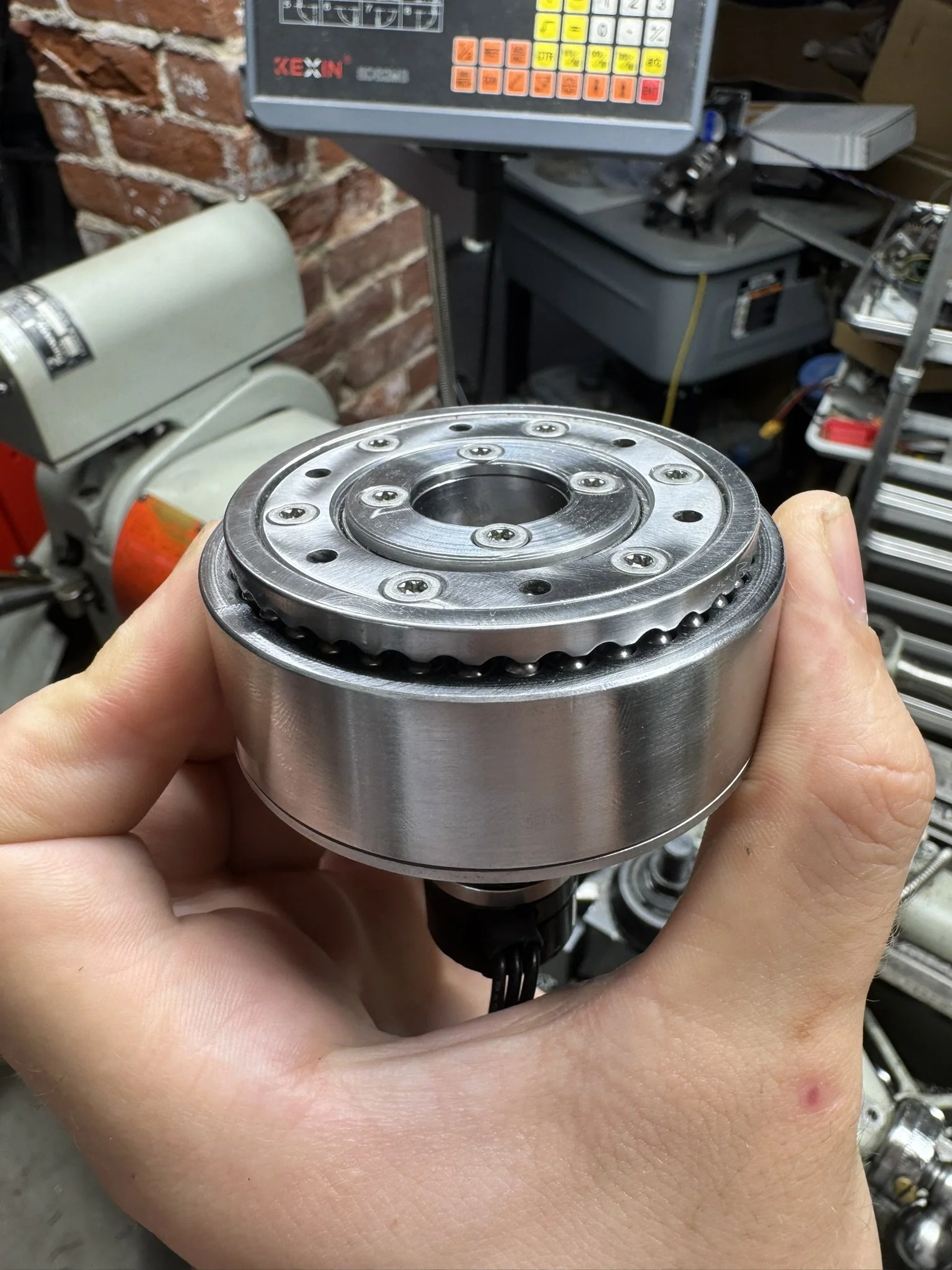
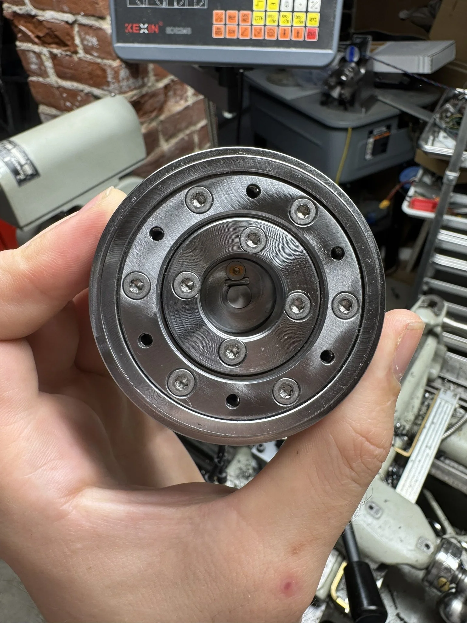
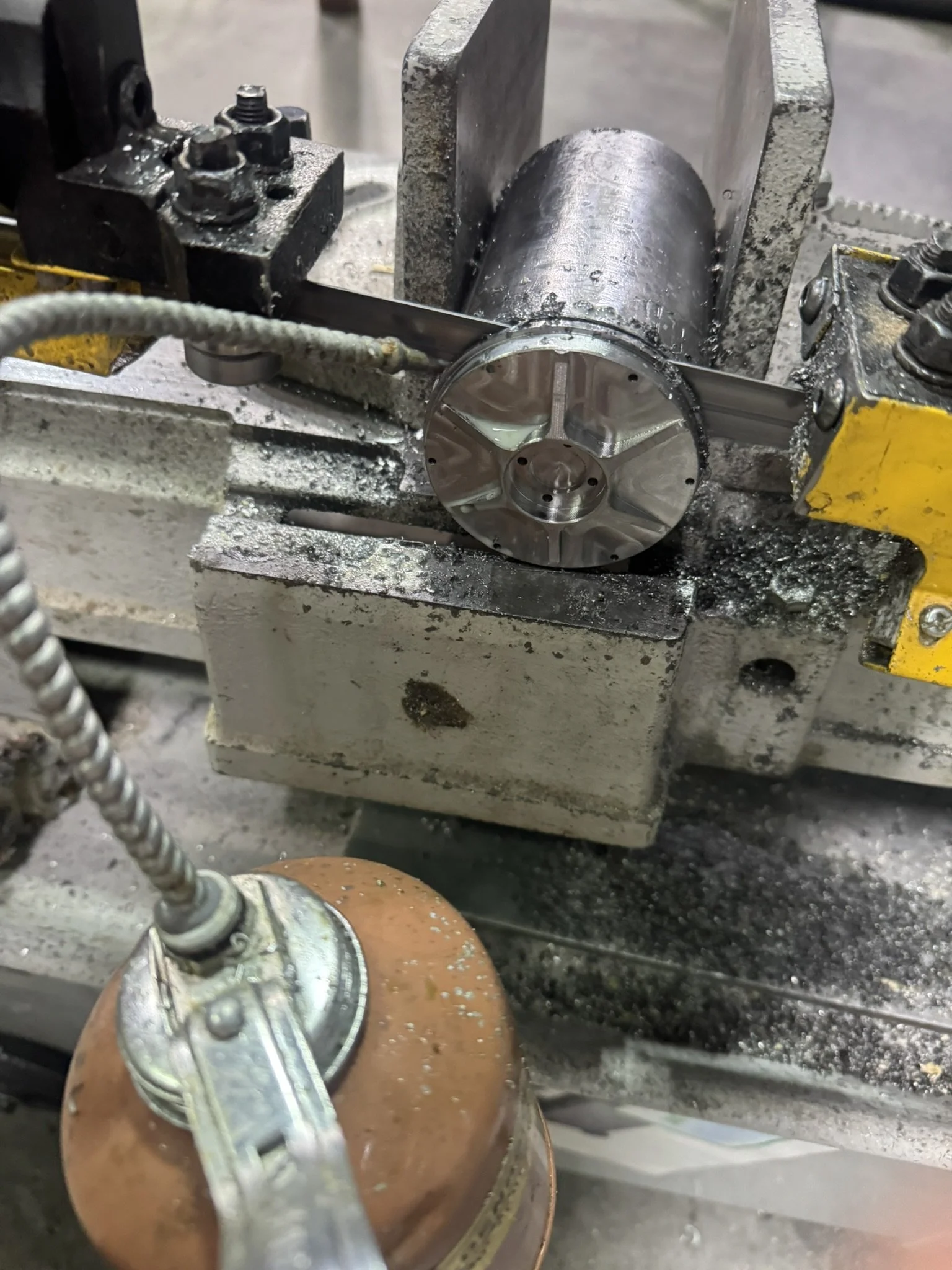
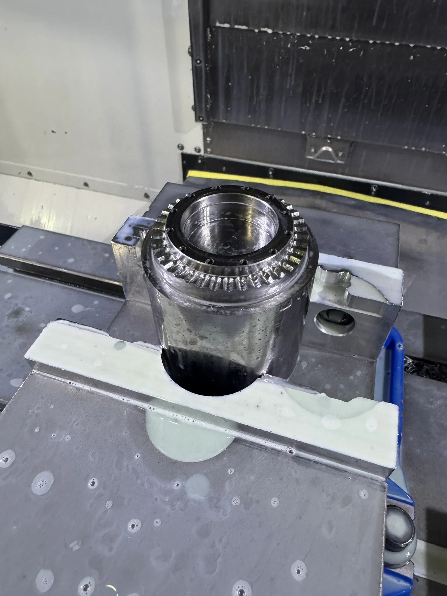
The concept is very similar to that of a harmonic drive: a cup-shaped input with a sinusoidal profile drives a set of balls up and down in cylinders, which protrude out and then engage with a groove-shaped plate. The number of balls and the number of grooves differ by one, producing a precessing motion of the groove plate. This design provides a very high reduction ratio, equal to the number of balls, in this case 38-to-one. As with a harmonic drive, it also can be designed to have a springlike backlash instead of a fixed clearance.
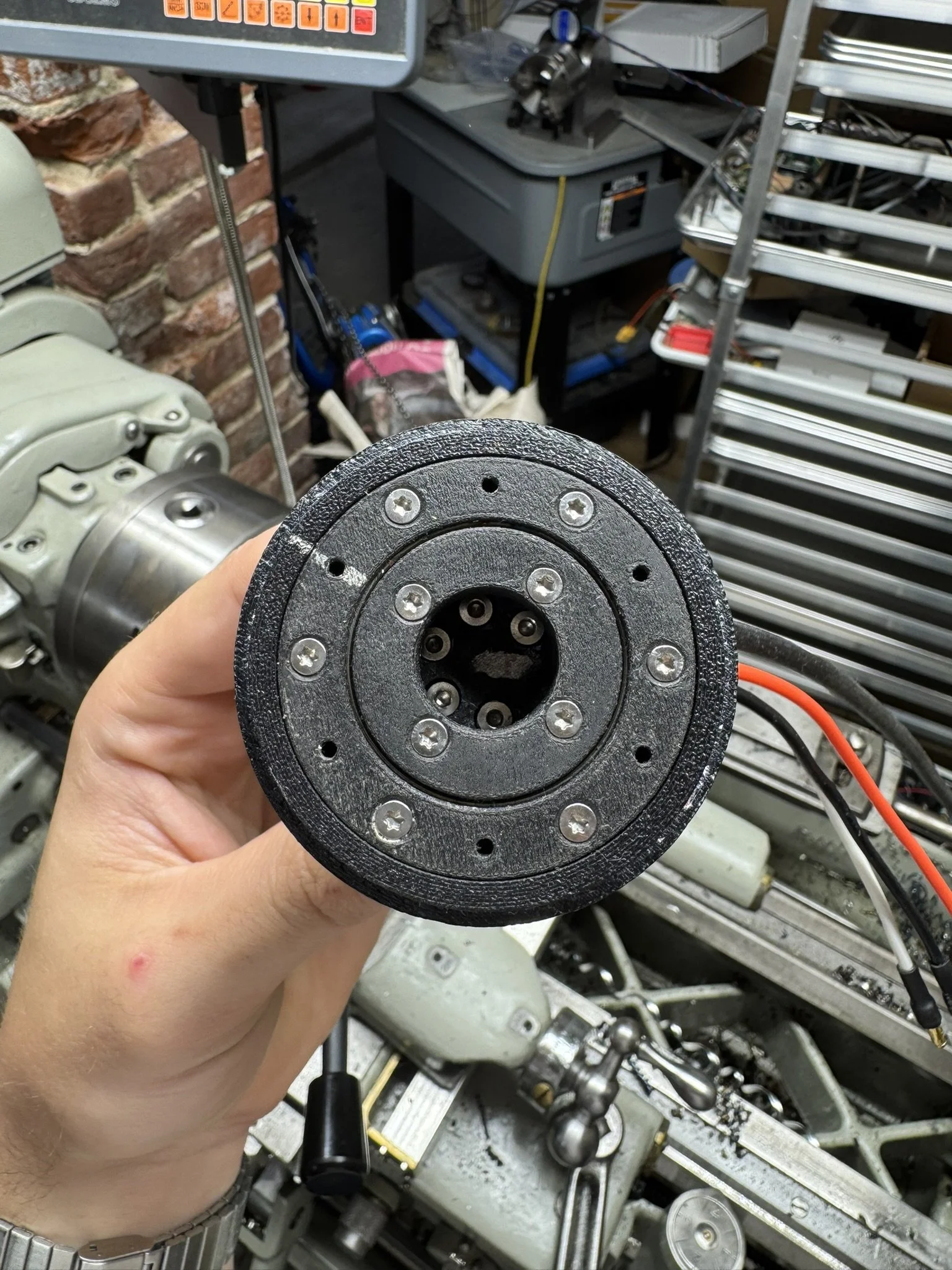
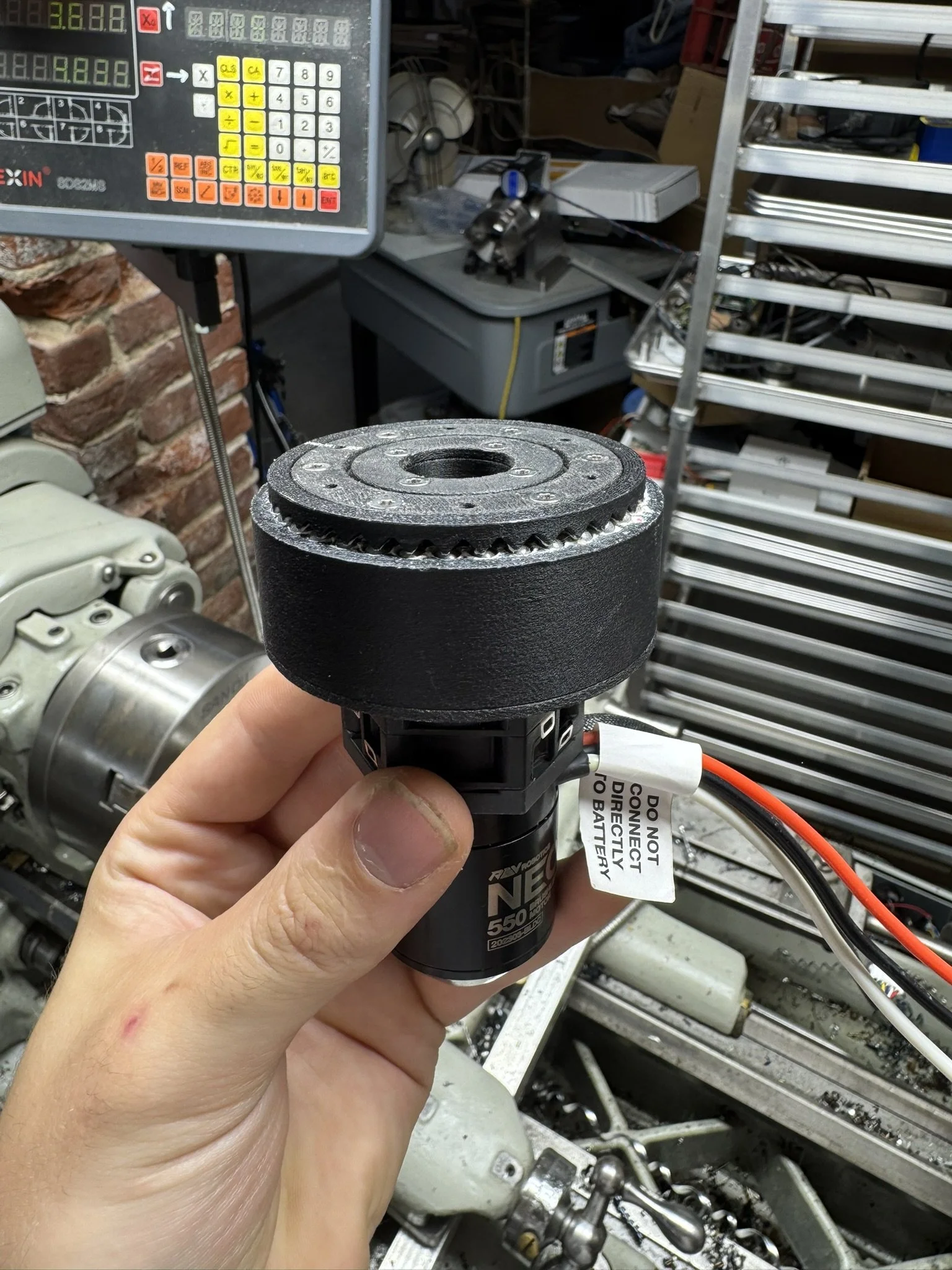
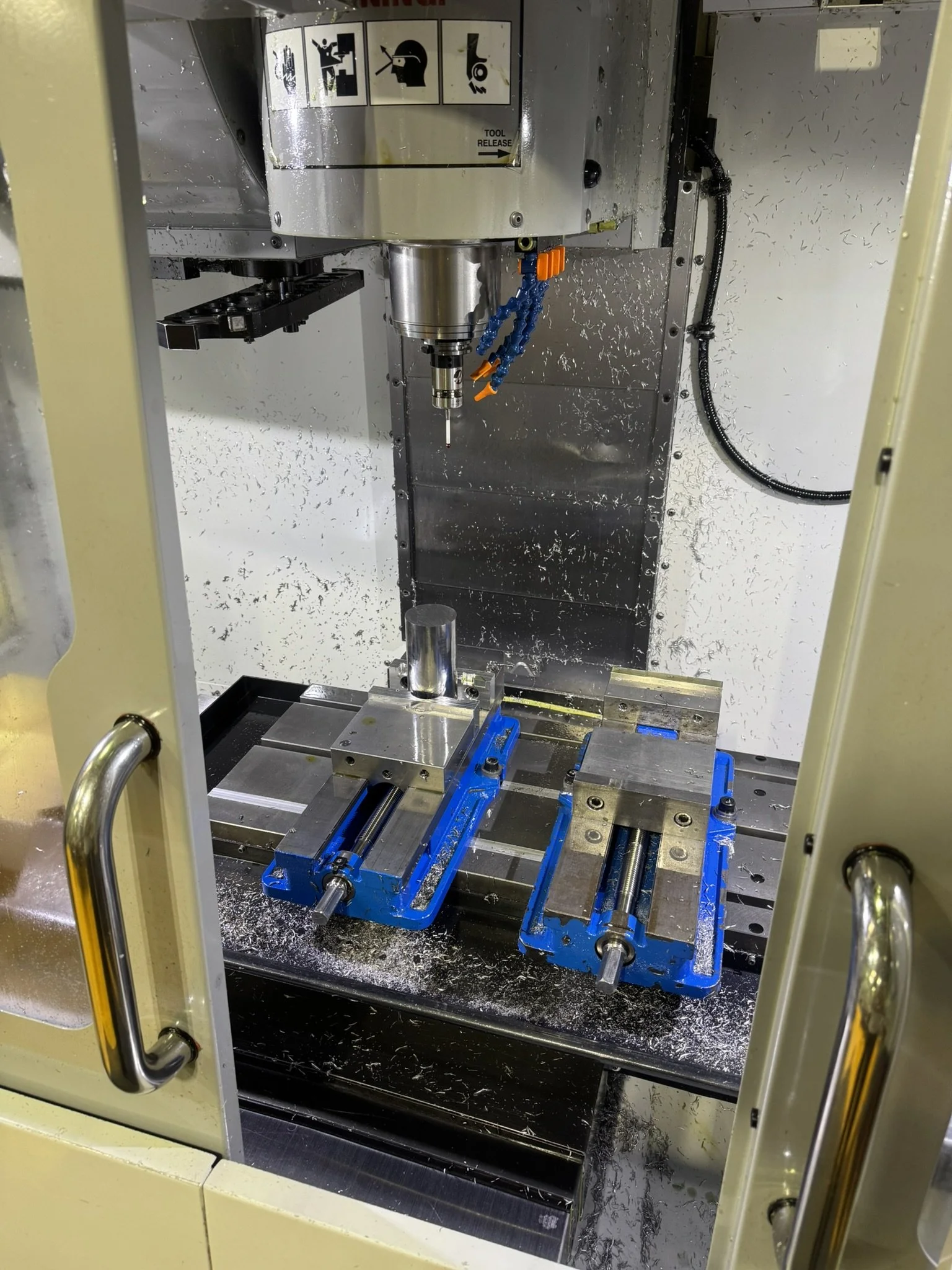
In the summer of 2024, I successfully designed a version of this ball reducer in CAD, and by the summer, I was able to 3D print it. To further challenge myself with tough materials and to understand the real-world performance of the ball reducer, I produced all the parts out of 4140 pre-hardened bearing-quality steel.
I still want to design test fixtures and a dynamometer to accurately assess its efficiency and backlash, but this project has already taught me a great deal about machining of hard materials and design.